
Gears
Herringbone gears: how they work and where they are used
A herringbone gear carries two opposing helices on the same face width. The two axial forces cancel each other at the middle of the face, and the tooth surface in mesh doubles. That is why it holds up in heavy, low-speed, high-power drives.
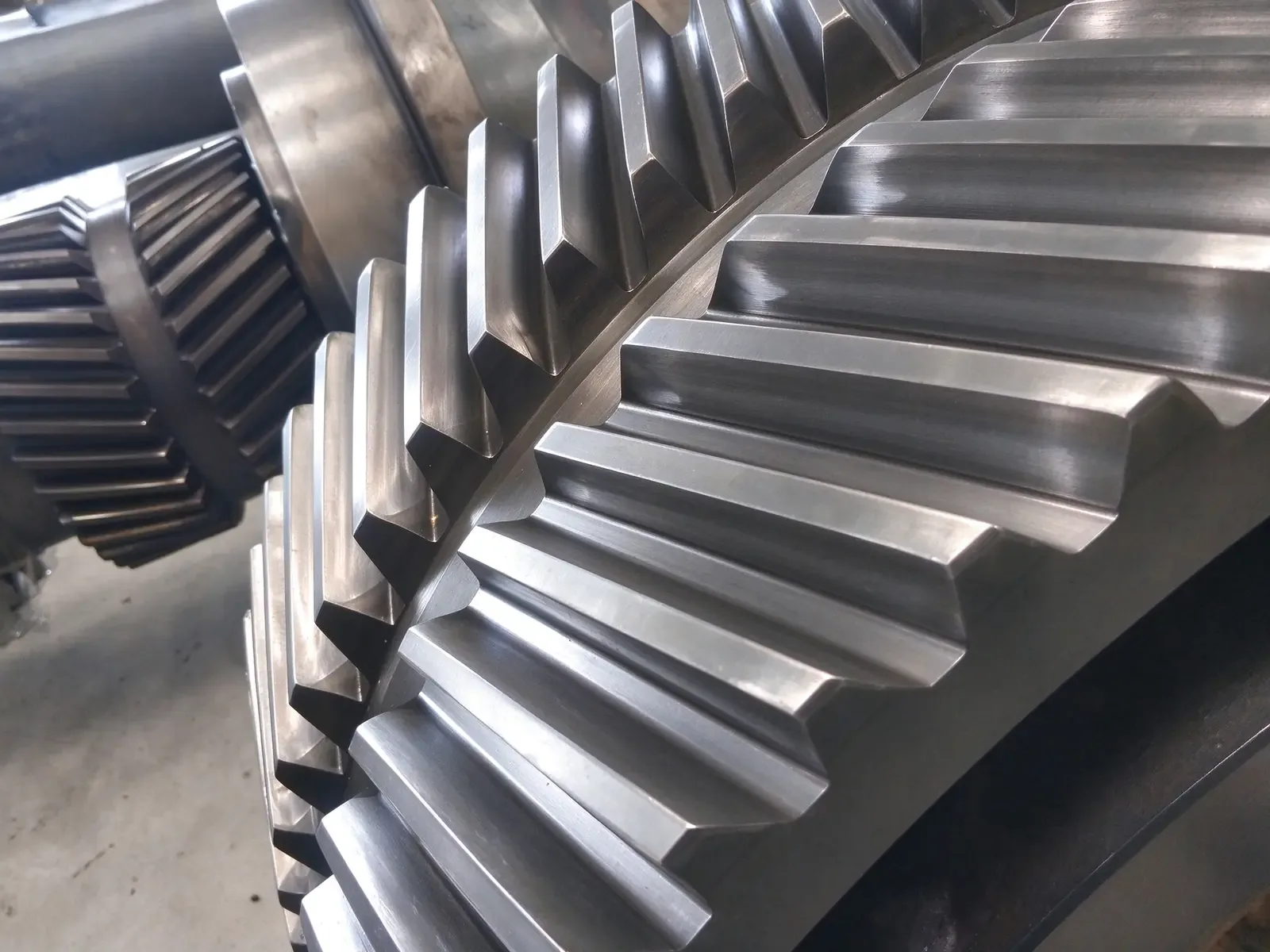
How the teeth are arranged
The tooth trace is made of two helices with the same helix angle but opposite hands, meeting at the middle of the face width. Depending on the cutter, they meet at an undercut groove or at an apex. In mesh both halves carry load at once, so the axial thrusts are equal and opposite, and cancel each other.
Three things follow. The bearings no longer carry axial load, so the shaft train can be shorter. More teeth are in mesh across the same face width, so contact stress is lower. And at a given center distance the housing is more compact than two separate helical gears placed back to back.
- 01
High load capacity
Load is shared by both helices, so root bending stress and contact stress are below those of a single helical gear of the same size. The same center distance carries more torque.
- 02
Smooth and quiet
Contact ratio is higher than a spur gear and the handover between teeth is gradual, so impact and vibration are low — which is what high-speed, heavily loaded or noise-sensitive drives need.
- 03
High efficiency
A well-cut and correctly assembled enclosed herringbone pair runs at about 97–99%. The losses are tooth sliding and oil churning.
- 04
Hard to make
Both helices must be aligned precisely: same helix angle, mirror-symmetric. Cutting needs a hob, shaper cutter or finger-type cutter that can run out, and hardened gears are usually ground afterwards.
Where they are used
Wherever the duty is low speed, heavy load and high power, and the housing has to stay compact, a herringbone gear has a place. The usual equipment:
- 01
Marine propulsion
The reduction gearbox carries propeller thrust and torque at the same time. A herringbone pair cancels the axial force inside the face width.
- 02
Power generation
Reduction units for hydro sets, wind-turbine gearboxes and reactor coolant pump drives run continuously and are judged on noise and reliability.
- 03
Mining and cement
Gearboxes for mills, crushers and rotary kilns see heavy shock loads; the tooth surface has to survive repeated overload.
- 04
Metallurgy and rolling
Rolling-mill main drives and sinter-plant drives combine high torque with frequent starts and stops.
- 05
Chemical and general heavy duty
Main drives for large compressors and blowers run continuously with long inspection intervals.
Where design and manufacturing get difficult
On paper a herringbone gear looks much like a helical gear. The difficulty is making the two halves of the face identical and symmetric.
- 01
Tooth form and alignment
Helix angle, tooth thickness and the meeting point must match. The undercut groove is set by the cutter radius: too narrow and the tooth trace cannot be cut through, too wide and usable face width is lost.
- 02
Material and heat treatment
42CrMo and 20CrMnTi are common. Case hardening brings the surface to HRC 58–62, but the distortion has to be corrected by press quenching, grinding or tooth correction.
- 03
Distortion control
Large-diameter rings warp in quenching and tempering. Symmetric loading, staged heating and a stress-relief step between roughing and finishing are more reliable than straightening afterwards.
- 04
Assembly and inspection
Center distance, shaft parallelism and backlash are rechecked in the assembled state. Accumulated pitch error turns directly into running noise, and a part that passes on its own does not prove the pair does.
What is changing
Three shifts are visible in herringbone gear work:
- 01
Hard-tooth grinding is routine
CNC form grinding and worm grinding now hold grade 6 on large-module herringbone gears, so post-hardening distortion is no longer absorbed by leaving extra stock.
- 02
Structure and process combined
Rings welded to their hubs, or rolled rings with less stock, shorten lead times on large parts and remove the error that comes from clamping two halves separately.
- 03
Condition monitoring
Vibration and temperature sensors in the gearbox use the two-sided force pattern of a herringbone gear to catch surface wear and tooth breakage earlier.
These notes describe processes we actually run. If you have a part to quote, send the drawing and we will answer with the process, the lead time and the tolerance we can hold.
Send drawing, get a quote