
Industry News
In-House Pre-Assembly of Split Girth Gears and the Nine-Step Assembly Method
The difficulty of large split girth gears lies not in machining individual pieces but in reassembling four segments into a single ring with accurate tooth alignment and concentricity. Keeping this step in-house leaves only bolting and re-measurement on site.
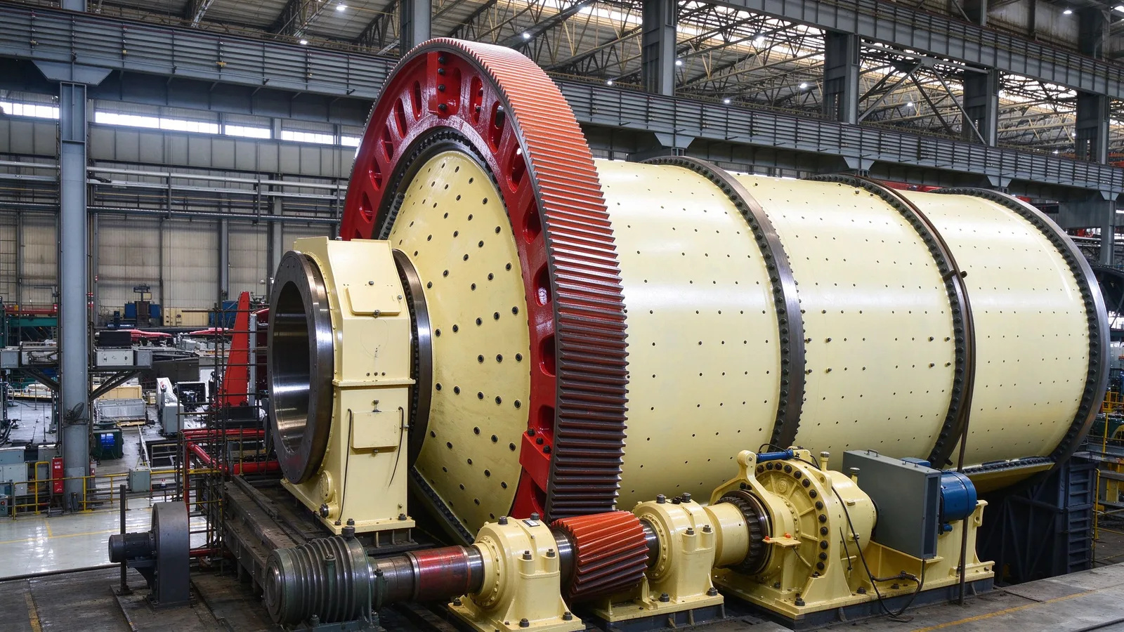
Why Split Girth Gears Should Be Pre-Assembled In-House
The large girth gear uses a four-segment structure. The four segments are first assembled in-house into two half-gears, lifted separately and bolted to the shell, then the full ring is closed into a complete large gear and adjusted for concentricity with the shell.
Keeping pre-assembly and trial running in-house means tooth alignment, concentricity and bolt-hole registration have already been verified before shipment, so on-site assembly steps are fewer and rework risk is lower.
Sequence of the Nine-Step Assembly Method
Jacking device layout → multi-section shell assembly (spigot location on end faces plus connection bolts tightened) → split girth gear assembly → shell lifting → end cover and hollow shaft bolting → bearing seat assembly → stepwise lowering of the shell assembly → girth gear installation → accessory installation and trial running.
After each step, measure before proceeding to the next; the coaxiality of the hollow shafts at both ends is checked with a laser tracker, and the bearing seats are also adjusted for equal height and concentricity with the laser tracker.
Synchronous Jacking and Lowering: Installation Without Large Lifting Equipment
Using synchronous jacking devices together with square boxes, square stools and shim plates in alternating layers, the shell is lowered as a whole onto the bearing seats, reducing the lifting capacity required; this also suits installation sites where the user has no large lifting equipment. Flush the bearing seats before each lowering step to prevent scoring of the copper bush; flush again when the clearance between the hollow shaft journal and the copper bush reaches 5 mm. As a reference for our capabilities, the maximum outer diameter for gear machining is Ø10 000 mm and the maximum module is within M60.
These notes describe processes we actually run. If you have a part to quote, send the drawing and we will answer with the process, the lead time and the tolerance we can hold.
Send drawing, get a quote