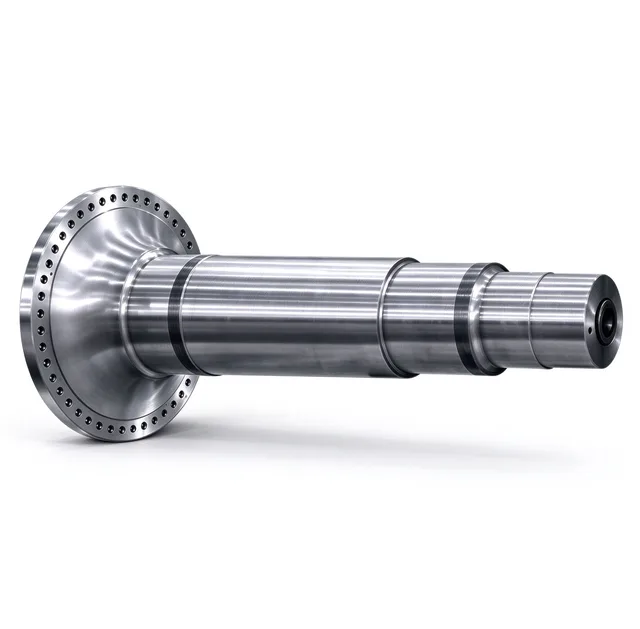
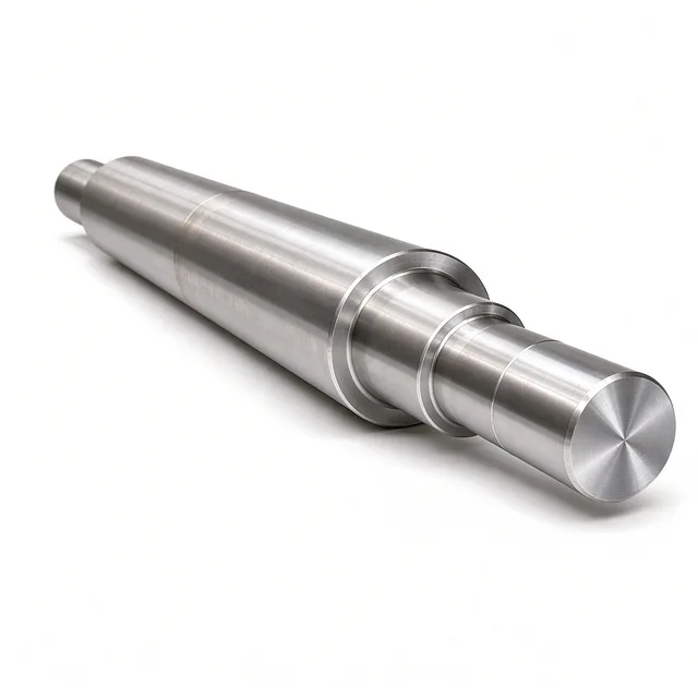
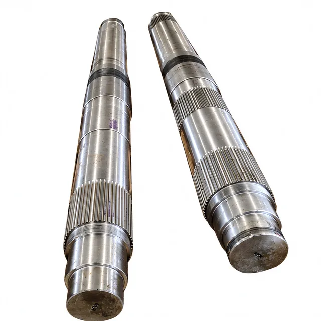
ShaftsHollow shafts
Ball Mill Hollow Shaft / Rotary Kiln Trunnion
Large one-piece hollow shaft with flanged ends and a precision-machined center journal, used as the support and material-passing component in ball mills and rotary kilns.
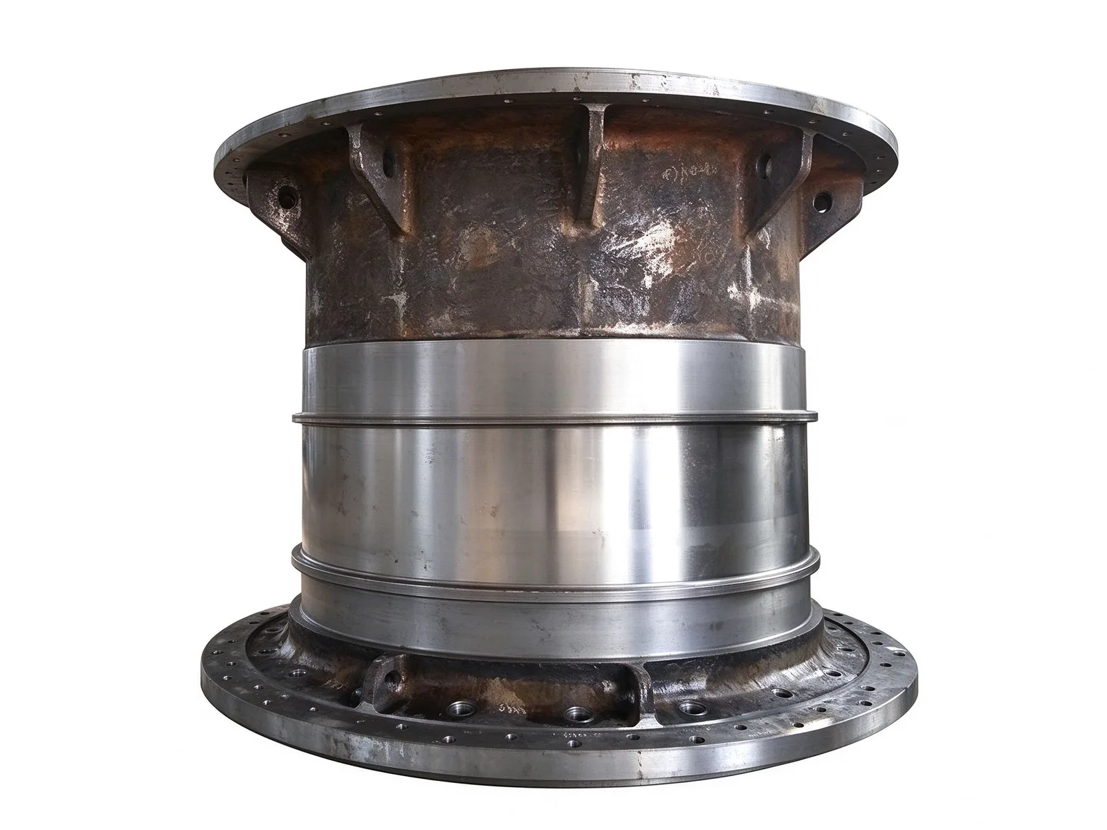
One-Piece Cast and Machined Body
The part is made as a single cast steel hollow body with top and bottom connecting flanges and reinforcing ribs. The upper flange connects to the feed or discharge arrangement, and the lower flange bolts to the mill shell end cover.
The center journal is finish-machined as the bearing support surface. The open bore allows material to pass through while the body carries the shell and material loads under continuous rotary operation.
Shaft Machining Scope
For shaft work, the shop can machine parts up to 10,000 mm in length including clamping and up to Ø1,500 mm in diameter. Journal tolerances can be held to h6 / IT7 with surface roughness to Ra 0.8 and radial runout within 0.02 mm.
Keyways, splines, threads, and end-face flange holes can be added according to the drawing. Quenching and tempering and high-frequency hardening are available for shaft parts.
Applications and Custom Options
This type of hollow shaft is commonly used in ball mills, rotary kilns, and other large horizontal rotary equipment in mining and building materials plants.
Customization follows the drawing: flange bolt pattern, bore diameter, journal dimensions, overall length, heat treatment, and inspection requirements are confirmed before production.
Inspection and Lead Time
Dimensions, journal tolerance, radial runout, and surface roughness are checked on the finished shaft. Heat treatment records and inspection reports can be provided as required.
Typical lead time for shaft parts is 8–12 weeks, depending on drawing review, material preparation, and machining sequence.
Specifications
- Max. machined length
- 10,000 mm (including clamping)
- Max. diameter
- Ø1,500 mm
- Journal tolerance
- h6 / IT7
- Surface roughness
- Ra 0.8
- Typical lead time
- 8–12 weeks
Common questions
- Can you machine this part to my drawing?
- Yes. Every part is quoted from the drawing. Send a PDF, DWG, DXF, STEP or IGES file with the material, quantity and any inspection requirements, and we reply within one working day.
- How are the material and heat treatment decided?
- They follow your drawing. The specification table shows the range normally used for this part type; the final material and heat treatment are confirmed with the quotation.
- What lead time and inspection come with the part?
- Lead time is set in the quotation and depends on material, size, quantity and inspection scope. Material verification, in-process checks and final inspection records are archived with the part, and any extra certification is agreed before production.
- How is the part packed for export?
- Export parts are rust-proofed and packed for the transport method and destination confirmed in the quotation, with lifting points and markings agreed before dispatch.
Every part is quoted from the drawing itself, not from a size band. Send it over and we answer with the process, the lead time and the tolerance we can hold.
Quote this part