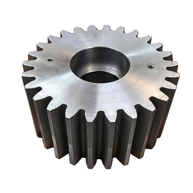
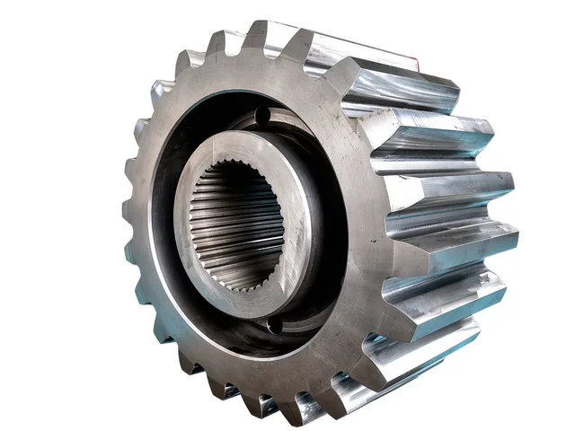
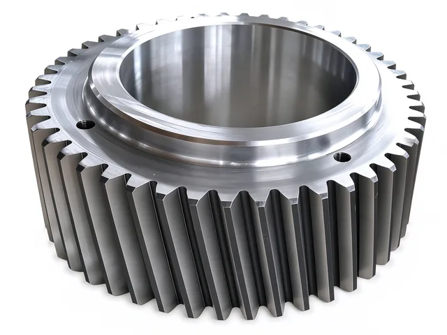
Gears & PinionsSpur gears
Parallel-Shaft Helical Gear Pair for Reducers
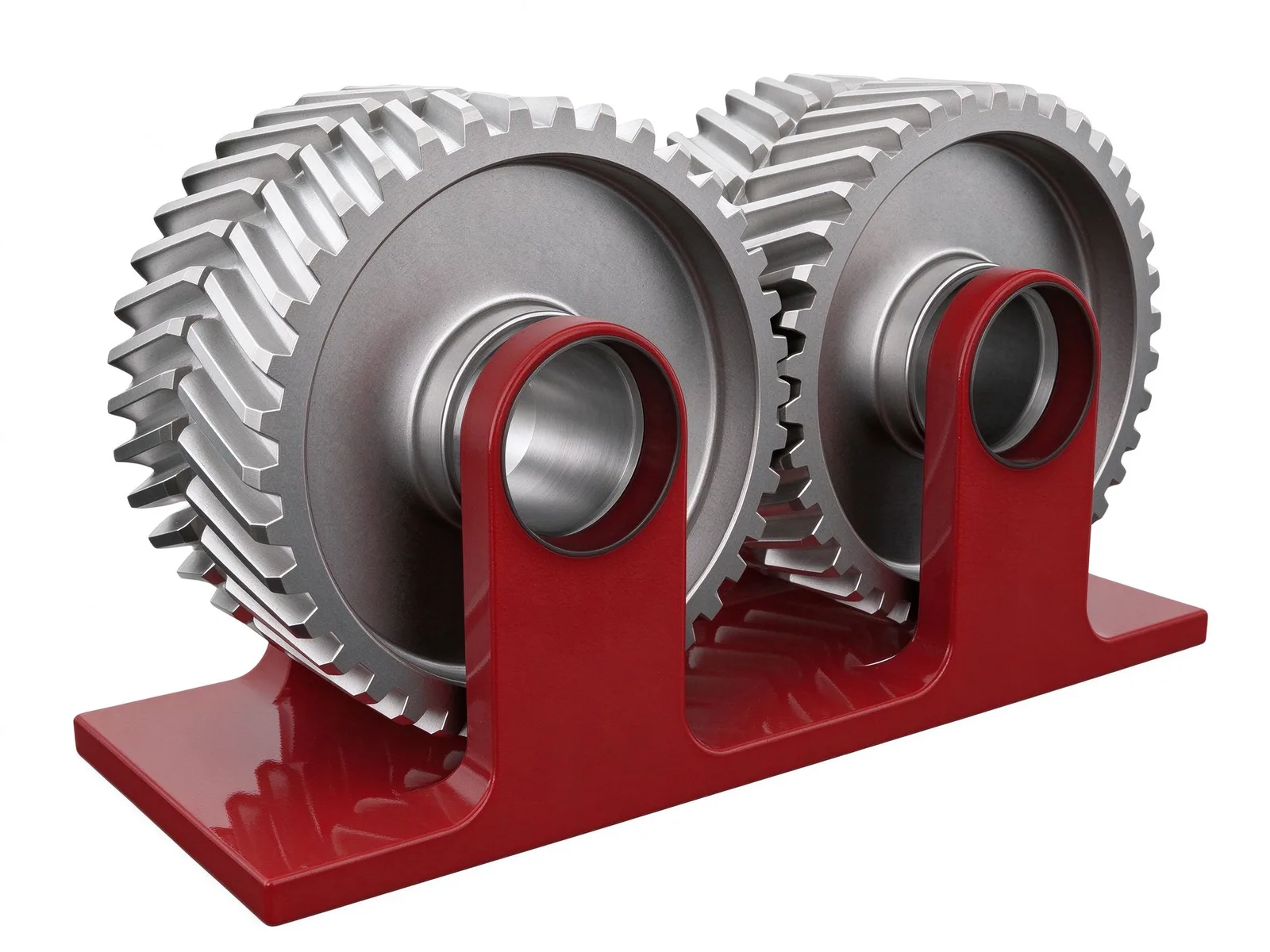
A parallel-shaft helical gear pair: the pinion takes the input and the large wheel drives the output, forming the single-stage reduction unit of an industrial gearbox. Made to drawing.
Gear cutting capacity
Spur, helical, herringbone and internal teeth are all cut in our own shop. The maximum outside diameter we can machine is Ø10 000 mm and the maximum module is M60, so a pinion and its mating wheel can be produced as a matched pair on the same equipment.
Blanks can come as steel castings, forgings or rolled rings; typical grades are 45#, 42CrMo and ZG270-500. Where the duty calls for a hard flank, teeth are ground after heat treatment.
How the pair works in a reduction box
The two gears sit on parallel axes with opposite helix angles: the small pinion is the input and the large wheel the output, so the mesh lowers speed and multiplies torque in one stage. The red bracket in the photo is a display fixture, not a working part.
Such pairs are commonly used in conveying machinery, metallurgy and mining plants, hoisting and transport equipment, and building-material or chemical drives. In service the gears are carried on their shafts in bearings inside a sealed housing and run in oil.
Inspection, heat treatment and customization
Hardening covers quench-and-temper as well as tooth-flank induction hardening, with a maximum quenching diameter of 10 000 mm. Pitch, runout, hardness and ultrasonic testing are carried out in-house before shipment.
The drawing sets module, number of teeth, helix angle, ratio, accuracy grade and flank hardness; we cut to the drawing rather than to a catalogue. Typical lead time for this type of gearing is within 90 days.
Specifications
- Max. outside diameter
- Ø10 000 mm
- Max. module
- M60
- Typical materials
- 45#, 42CrMo, ZG270-500
- Heat treatment
- Quench and temper + tooth-flank induction hardening
- Typical lead time
- Within 90 days
Common questions
- Can you machine this part to my drawing?
- Yes. Every part is quoted from the drawing. Send a PDF, DWG, DXF, STEP or IGES file with the material, quantity and any inspection requirements, and we reply within one working day.
- How are the material and heat treatment decided?
- They follow your drawing. The specification table shows the range normally used for this part type; the final material and heat treatment are confirmed with the quotation.
- What lead time and inspection come with the part?
- Lead time is set in the quotation and depends on material, size, quantity and inspection scope. Material verification, in-process checks and final inspection records are archived with the part, and any extra certification is agreed before production.
- How is the part packed for export?
- Export parts are rust-proofed and packed for the transport method and destination confirmed in the quotation, with lifting points and markings agreed before dispatch.
Every part is quoted from the drawing itself, not from a size band. Send it over and we answer with the process, the lead time and the tolerance we can hold.
Quote this part