Other OEM PartsAssemblies
Ball Mill End Cover Assembly
Welded steel end cover assembly for ball and rod mills. It mates with the mill shell to form a closed grinding chamber and carries the trunnion support interface.
Structure and load path
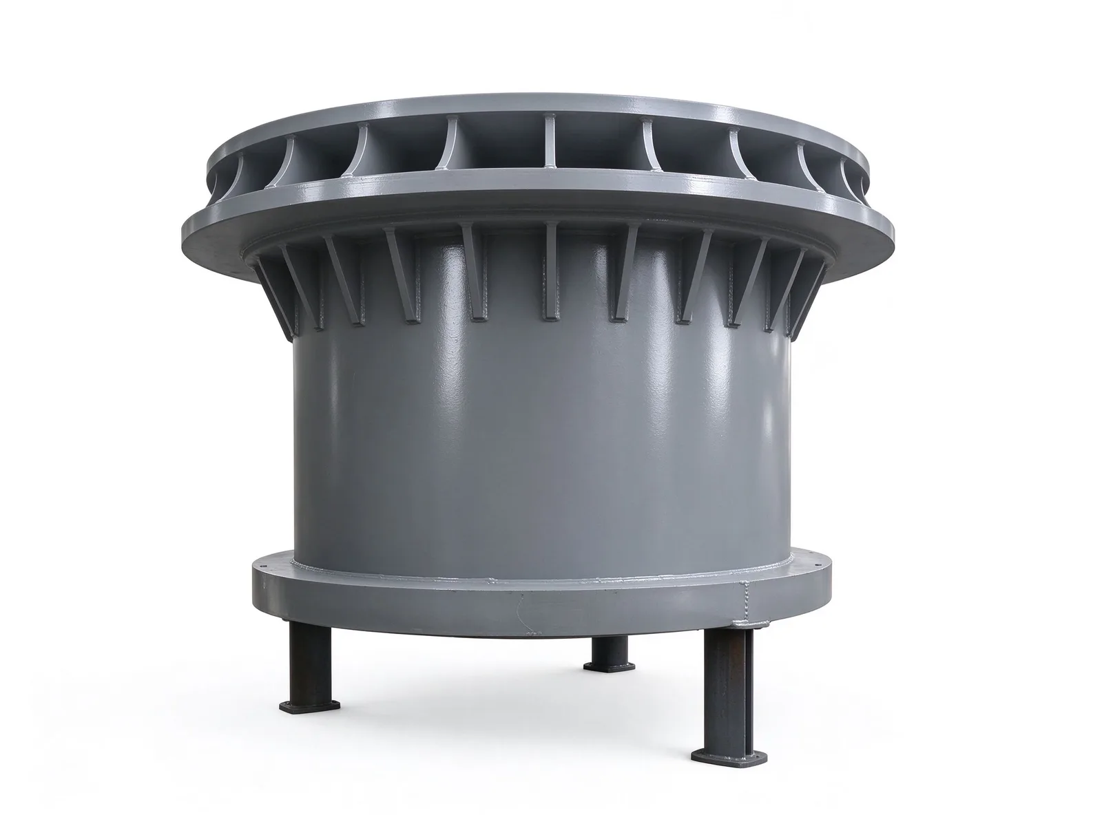
The end cover is welded from heavy steel plate into a flanged cylindrical pressure structure. A ring of radial stiffener ribs sits around the large top flange to raise joint stiffness and resistance to deformation.
In service the top flange is bolted and mated to the mill shell, so the cover and shell together absorb the dynamic and impact loads of grinding. This is a core load-bearing part for heavy-duty, continuous operation.
Centre interface and machining
The centre of the cover is hollow and takes the trunnion, the feed spiral or the discharge device. It serves both as the mounting datum for the mill's rotary support and as the passage for material and air into and out of the grinding chamber. Flange faces, spigots and bolt holes are machined to drawing to hold mating accuracy with the shell. The short columns at the bottom are temporary storage and painting supports, not part of the working structure.
Quality control and custom range
After welding, flange faces, spigots and connection holes are machined to drawing, with flatness and bolt-hole position controlled and gauge or inspection records available on request. Weld seams are inspected visually and by the non-destructive method agreed in the technical protocol.
End covers are built to customer drawings. Feed end covers, discharge end covers and sizes for different shell diameters all fall within the custom range; material grade, plate thickness, welding procedure and inspection level are fixed by the drawing and technical agreement.
Specifications
- Structure
- Welded heavy steel plate, flanged cylindrical pressure structure
- Top flange
- Large-diameter flange with a ring of radial stiffener ribs
- Centre interface
- Hollow; takes trunnion, feed spiral or discharge device
Common questions
- Can you machine this part to my drawing?
- Yes. Every part is quoted from the drawing. Send a PDF, DWG, DXF, STEP or IGES file with the material, quantity and any inspection requirements, and we reply within one working day.
- How are the material and heat treatment decided?
- They follow your drawing. The specification table shows the range normally used for this part type; the final material and heat treatment are confirmed with the quotation.
- What lead time and inspection come with the part?
- Lead time is set in the quotation and depends on material, size, quantity and inspection scope. Material verification, in-process checks and final inspection records are archived with the part, and any extra certification is agreed before production.
- How is the part packed for export?
- Export parts are rust-proofed and packed for the transport method and destination confirmed in the quotation, with lifting points and markings agreed before dispatch.
Every part is quoted from the drawing itself, not from a size band. Send it over and we answer with the process, the lead time and the tolerance we can hold.
Quote this part