Other OEM PartsAssemblies
Ball Mill Shell
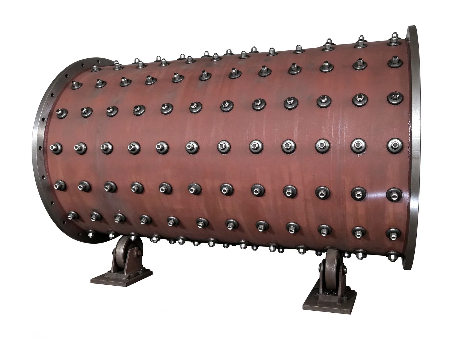
A horizontal ball mill shell rolled and welded from thick steel plate. Flanged ends locate the end covers and trunnions, and bolts on the outer wall clamp the wear liners.
Shell Structure and Machining
The shell is a heavy load-bearing cylinder rolled from thick steel plate and closed with longitudinal and circumferential welds. The flange rings welded to both ends are machined as assembly datums, so that the feed and discharge end covers, the trunnions and the transmission girth gear can be fitted and aligned against them.
Flange faces are machined after welding, and bolt hole patterns are drilled to the drawing, so that the shell seats squarely on the end covers and transmits torque to the girth gear without shimming on site.
Liners and Bolted Fixing
The rows of bolts on the outer wall are liner tension bolts. They clamp the wear liners to the inside of the shell from outside, keeping the shell plate away from grinding media and material impact.
Liner material is selected with the customer, typically high-manganese steel, high-chromium cast iron or wear-resistant rubber. The liner profile also controls how the grinding balls are lifted and dropped, which is part of the grinding efficiency.
Assembly and Inspection
The shell is assembled on roller stands in our workshop so that it turns slowly in place, letting operators fit liners and tighten bolts all the way round at a fixed station instead of working on a suspended drum. The roller stands are assembly tooling and are not part of the delivered machine.
Before shipment we check the flange mating faces, the bolt tightening sequence and the weld appearance, and we confirm the liner and end-cover interfaces against the drawing.
Customization Scope
Diameter, length, effective volume and throughput capacity follow the mill specification or the customer's drawing; send us the technical parameters and we will match the shell and its interfaces to them.
Liner material and profile, matched drive power and the end-cover connection are confirmed together with the working conditions — the ore or material to be ground and the duty cycle. We do not infer these from a photo.
Specifications
- Structure
- One-piece welded rotary shell with flanged ends
- Shell forming
- Rolled and welded from thick steel plate
- Liner fixing
- Tension bolts on the outer wall hold internal liners
- Liner material options
- High-manganese steel, high-chromium cast iron, wear-resistant rubber
- Assembly
- Roller stands turn the shell for full-circle liner fitting
Common questions
- Can you machine this part to my drawing?
- Yes. Every part is quoted from the drawing. Send a PDF, DWG, DXF, STEP or IGES file with the material, quantity and any inspection requirements, and we reply within one working day.
- How are the material and heat treatment decided?
- They follow your drawing. The specification table shows the range normally used for this part type; the final material and heat treatment are confirmed with the quotation.
- What lead time and inspection come with the part?
- Lead time is set in the quotation and depends on material, size, quantity and inspection scope. Material verification, in-process checks and final inspection records are archived with the part, and any extra certification is agreed before production.
- How is the part packed for export?
- Export parts are rust-proofed and packed for the transport method and destination confirmed in the quotation, with lifting points and markings agreed before dispatch.
Every part is quoted from the drawing itself, not from a size band. Send it over and we answer with the process, the lead time and the tolerance we can hold.
Quote this part