Gears & PinionsGear shafts
Custom Precision Worm Gear and Worm Shaft Set
Precision worm gear pair for 90° crossed-shaft drives: a hardened, ground steel worm in one piece with its shaft and a copper-alloy wheel with a bolted flange rim. High ratio, self-locking duty.
Structure and machining
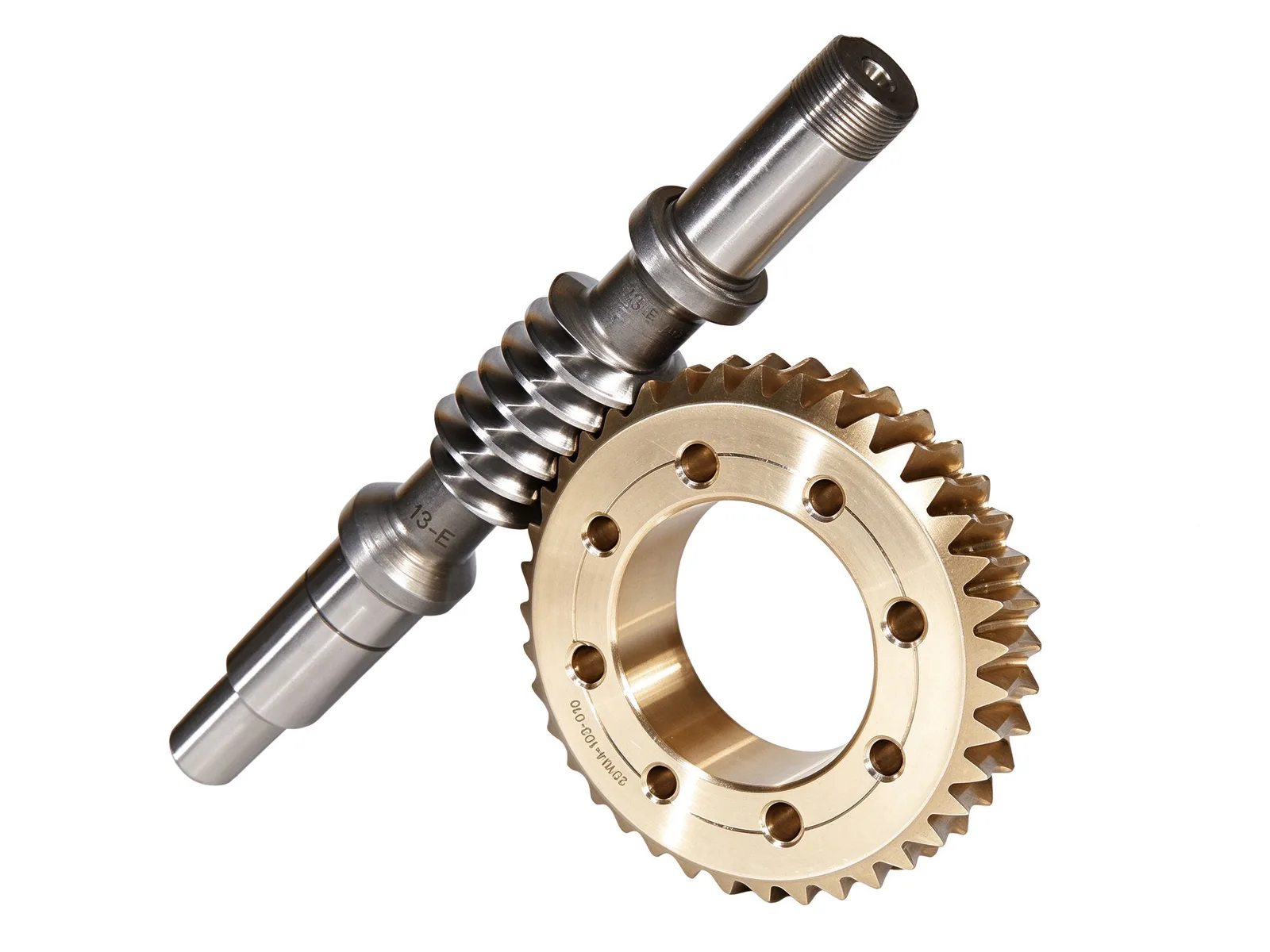
The worm is made in one piece with its shaft: the helical thread is cut directly on the alloy steel shaft, then case hardened and precision ground. Stepped journals with locating shoulders at both ends carry the bearings, and an external thread at the shaft end is used for locking. The worm wheel is a copper-alloy body whose curved teeth match the worm helix; its central flange carries a ring of bolt holes so the rim can be bolted to the output hub and replaced on its own once worn.
Transmission behaviour and working conditions
A worm pair transmits between shafts at 90° and reaches a large reduction ratio in a single stage, which keeps the housing compact. When the lead angle is smaller than the friction angle of the contact surfaces, the pair is self-locking and blocks reverse drive from the load, so it also works as a safety brake. The copper-to-steel sliding contact runs smoothly with low impact, but efficiency is lower than in parallel-shaft gear drives. The pair is commonly used in worm reducers, machine-tool indexing mechanisms, hoisting equipment, valve actuators, automated conveyor lines and medical transmission mechanisms — working conditions with a high ratio, low speed, high torque and a self-locking requirement.
Quality control
Tooth pitch, runout, hardness and ultrasonic inspection are all checked in-house. Our gear machining capacity reaches Ø10 000 mm outside diameter and module M60, with hardening diameters up to Ø10 000 mm; blanks can be castings, forgings or rolled rings.
Customisation and lead time
Number of worm starts, module, lead angle, wheel tooth count, ratio and accuracy grade are set against the customer's drawing or sample. The steel grade and tooth-surface hardness of the worm, and the specific copper-alloy grade of the wheel, are agreed in the material technical file. Typical lead time is within 90 days.
Specifications
- Max. outside diameter
- Ø10 000 mm
- Max. module
- M60
- Heat treatment
- Quenching and tempering, tooth-surface induction hardening
- Quality control
- Tooth pitch, runout, hardness and UT checked in-house
- Typical lead time
- Within 90 days
Common questions
- Can you machine this part to my drawing?
- Yes. Every part is quoted from the drawing. Send a PDF, DWG, DXF, STEP or IGES file with the material, quantity and any inspection requirements, and we reply within one working day.
- How are the material and heat treatment decided?
- They follow your drawing. The specification table shows the range normally used for this part type; the final material and heat treatment are confirmed with the quotation.
- What lead time and inspection come with the part?
- Lead time is set in the quotation and depends on material, size, quantity and inspection scope. Material verification, in-process checks and final inspection records are archived with the part, and any extra certification is agreed before production.
- How is the part packed for export?
- Export parts are rust-proofed and packed for the transport method and destination confirmed in the quotation, with lifting points and markings agreed before dispatch.
Every part is quoted from the drawing itself, not from a size band. Send it over and we answer with the process, the lead time and the tolerance we can hold.
Quote this part