Gears & PinionsGear shafts
Girth Gear Pinion Shaft Assembly for Mills and Kilns
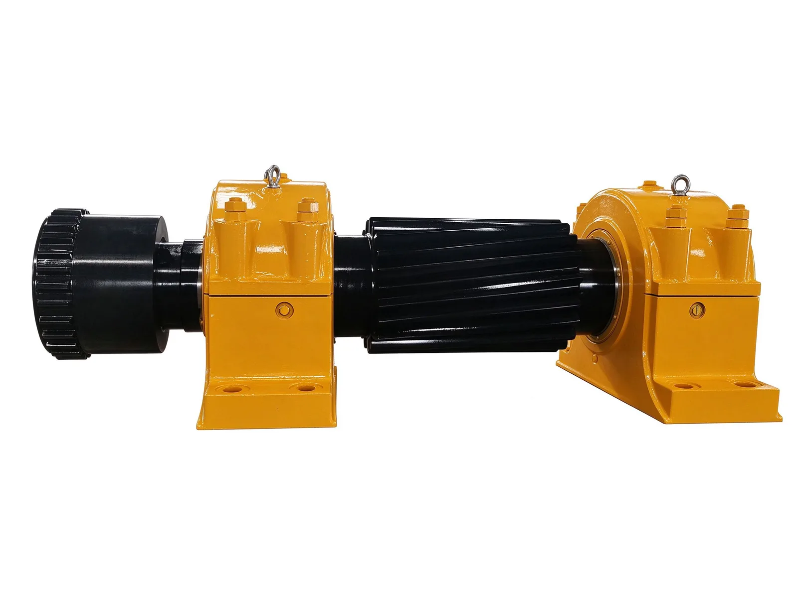
Pinion shaft assembly for the girth-gear drive of ball mills, rotary kilns and dryers: helical pinion, split bearing housings and a drum gear coupling at the input end.
Construction of the assembly
The helical pinion sits in the centre, its teeth meshing with the large girth gear fixed to the shell and transmitting the reducer output to the shell. Compared with straight teeth, the helical form gives a higher contact ratio and smoother running. Straight, helical, herringbone and internal teeth can all be cut in-house, up to module M60.
The pinion shaft is carried on two split heavy-duty bearing housings in a double-supported arrangement that takes radial and axial loads; the split design allows bearings to be replaced during maintenance without dismantling the whole shaft. The input end carries the outer sleeve of a drum-type gear coupling, which compensates for installation error and axial float.
Machining capability
Gear parts up to Ø10 000 mm outside diameter, with straight, helical, herringbone or internal teeth; maximum hardening diameter 10 000 mm. Typical materials are 45#, 42CrMo and ZG270-500, with quenching and tempering plus induction hardening of the tooth flanks available.
Blanks can be castings, forgings or rolled rings, chosen against the drawing and the duty. Assembly, alignment and trial running of the pinion shaft assembly are carried out in our own works, and tooth pitch, runout and hardness are recorded before shipment.
Quality control and customization
Tooth pitch, runout, hardness and ultrasonic inspection are done in-house, with dimensions and geometry checked against the drawing; split faces, joint faces and journal fits are measured part by part.
Tooth geometry, shaft extension, coupling interface and the flange at the drive end (for an auxiliary drive or a speed measuring device) can be customized to the project; typical lead time is within 90 days.
Specifications
- Max. outside diameter
- Ø10 000 mm
- Max. module
- Up to M60
- Typical materials
- 45#, 42CrMo, ZG270-500
- Heat treatment
- Quenching and tempering, tooth surface induction hardening
- Typical lead time
- Within 90 days
Common questions
- Can you machine this part to my drawing?
- Yes. Every part is quoted from the drawing. Send a PDF, DWG, DXF, STEP or IGES file with the material, quantity and any inspection requirements, and we reply within one working day.
- How are the material and heat treatment decided?
- They follow your drawing. The specification table shows the range normally used for this part type; the final material and heat treatment are confirmed with the quotation.
- What lead time and inspection come with the part?
- Lead time is set in the quotation and depends on material, size, quantity and inspection scope. Material verification, in-process checks and final inspection records are archived with the part, and any extra certification is agreed before production.
- How is the part packed for export?
- Export parts are rust-proofed and packed for the transport method and destination confirmed in the quotation, with lifting points and markings agreed before dispatch.
Every part is quoted from the drawing itself, not from a size band. Send it over and we answer with the process, the lead time and the tolerance we can hold.
Quote this part