Bearings & Machined PartsCouplings
Drum Gear Coupling
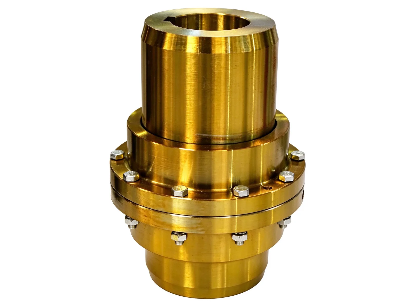
Drum gear coupling built from two crowned external-tooth hubs joined by bolted internal-tooth flanges. It links two shafts, carries high torque and compensates radial, angular and axial misalignment.
Structure and assembly
The coupling consists of two half-coupling hubs with external teeth and two internally toothed flanged rings, clamped together by high-strength bolts. Each hub bore is keyed to the driving or driven shaft, so torque passes through the key and then through the meshing teeth.
The external teeth are crowned along the tooth width. This crowning lets the teeth articulate inside the internal ring and keeps the mesh working when the two shafts sit at a small angle or offset.
Misalignment and load capacity
The crowned tooth mesh accepts radial, angular and axial installation offsets at the same time, absorbing assembly error, thermal growth in service and foundation settlement. Because the load is carried by meshing teeth rather than an elastomer, the coupling transmits noticeably higher torque and resists shock loads better than elastic couplings.
Lubrication, maintenance and machining to drawing
The internal cavity can be packed with grease or fed with gear oil to keep the tooth flanks lubricated and wear low. The split flanged body with bolted joints allows on-site assembly, disassembly and inspection without moving the connected machines.
Bores, keyways, flange bolt positions and overall length are machined to the customer's drawing; the specific model, rated torque and permissible misalignment are agreed with the buyer from the shaft data before production starts.
Specifications
- Design
- Two crowned external-tooth hubs and two internal-tooth flanged rings, bolted
- Bore connection
- Keyway and key on driving and driven shaft
- Misalignment compensation
- Radial, angular and axial
- Lubrication
- Grease packing or gear oil in the internal cavity
Common questions
- Can you machine this part to my drawing?
- Yes. Every part is quoted from the drawing. Send a PDF, DWG, DXF, STEP or IGES file with the material, quantity and any inspection requirements, and we reply within one working day.
- How are the material and heat treatment decided?
- They follow your drawing. The specification table shows the range normally used for this part type; the final material and heat treatment are confirmed with the quotation.
- What lead time and inspection come with the part?
- Lead time is set in the quotation and depends on material, size, quantity and inspection scope. Material verification, in-process checks and final inspection records are archived with the part, and any extra certification is agreed before production.
- How is the part packed for export?
- Export parts are rust-proofed and packed for the transport method and destination confirmed in the quotation, with lifting points and markings agreed before dispatch.
Every part is quoted from the drawing itself, not from a size band. Send it over and we answer with the process, the lead time and the tolerance we can hold.
Quote this part