ShaftsTransmission shafts
Heavy-Duty Flanged Output Main Shaft
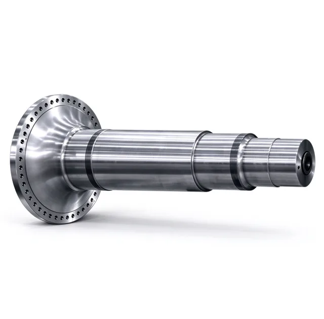
A one-piece forged output main shaft with an integral mounting flange and a multi-step stepped body, machined for heavy reducers, mills and crushers.
Structure and load path
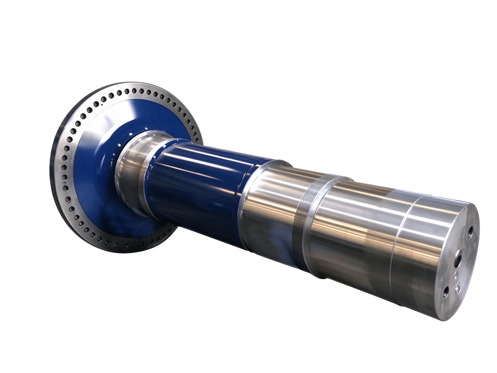
The flange at one end is forged integrally with the shaft body rather than bolted or shrunk on, so torque from the drive is carried through a continuous steel section. A ring of evenly spaced bolt holes on the flange face mates with drum covers, rotary tables or crusher housings and keeps the joint concentric under high torque.
The shaft body is machined as a multi-step profile. Ground journals act as bearing and seal seats, locating the shaft axially and radially inside the reducer housing, while the enlarged sections raise torsional stiffness against shock and reversing loads.
Machining and surface treatment
Fits and seal seats are precision ground to hold the bearing seat tolerance called out on the drawing, and the shaft end carries a center hole used as the datum for turning and grinding as well as for lifting and axial locking during assembly.
Non-fitting surfaces receive a blue anti-corrosion coating to suit dusty and humid plant conditions. Keyways, splines, threads and end-face flange holes can be added per drawing. Shaft machining capacity reaches a maximum length of 10 000 mm including clamping, a maximum diameter of Ø1 500 mm and a single-piece weight of up to 8 t; journal tolerance h6 / IT7, surface roughness Ra 0.8 and radial runout ≤0.02 mm are held on request.
Materials and heat treatment
The shaft is typically forged from 42CrMo or 40CrNiMo alloy structural steel as a single piece, then quenched and tempered to balance strength, toughness and resistance to alternating shock loads. Critical fits can be surface hardened after machining.
Typical lead time is 8–12 weeks depending on size and quantity. Drawing review covers material certification, heat treatment records and dimensional inspection before shipment.
Applications and customization
This type of shaft is commonly used as the core drive component in heavy-duty gear reducers, ball mills, roller presses, rotary kilns and large crushers, where it transmits torque and supports shaft rotation at the same time.
Flange diameter, bolt hole pattern, journal diameters and overall length are made to the customer's drawing; material grade, heat treatment and rated torque are confirmed against the technical data before production. Please send the drawing or the mating equipment details so the shaft can be matched to the mounting interface.
Specifications
- Material
- 42CrMo / 40CrNiMo alloy structural steel
- Configuration
- Integral forged flange with multi-step stepped shaft body
- Heat treatment
- Quenching and tempering, optional surface hardening on fits
- Fitting surfaces
- Precision ground journals and seal seats
- Non-fitting surfaces
- Anti-corrosion coating
- Shaft end
- Center hole plus threaded holes for axial locking and lifting
Common questions
- Can you machine this part to my drawing?
- Yes. Every part is quoted from the drawing. Send a PDF, DWG, DXF, STEP or IGES file with the material, quantity and any inspection requirements, and we reply within one working day.
- How are the material and heat treatment decided?
- They follow your drawing. The specification table shows the range normally used for this part type; the final material and heat treatment are confirmed with the quotation.
- What lead time and inspection come with the part?
- Lead time is set in the quotation and depends on material, size, quantity and inspection scope. Material verification, in-process checks and final inspection records are archived with the part, and any extra certification is agreed before production.
- How is the part packed for export?
- Export parts are rust-proofed and packed for the transport method and destination confirmed in the quotation, with lifting points and markings agreed before dispatch.
Every part is quoted from the drawing itself, not from a size band. Send it over and we answer with the process, the lead time and the tolerance we can hold.
Quote this part