Gears & PinionsGear shafts
Heavy-Duty Integrated Spur Gear Shaft
One-piece heavy-duty spur gear shaft used as the driving pinion of industrial transmission systems, transmitting high torque and taking shock loads at low speed.
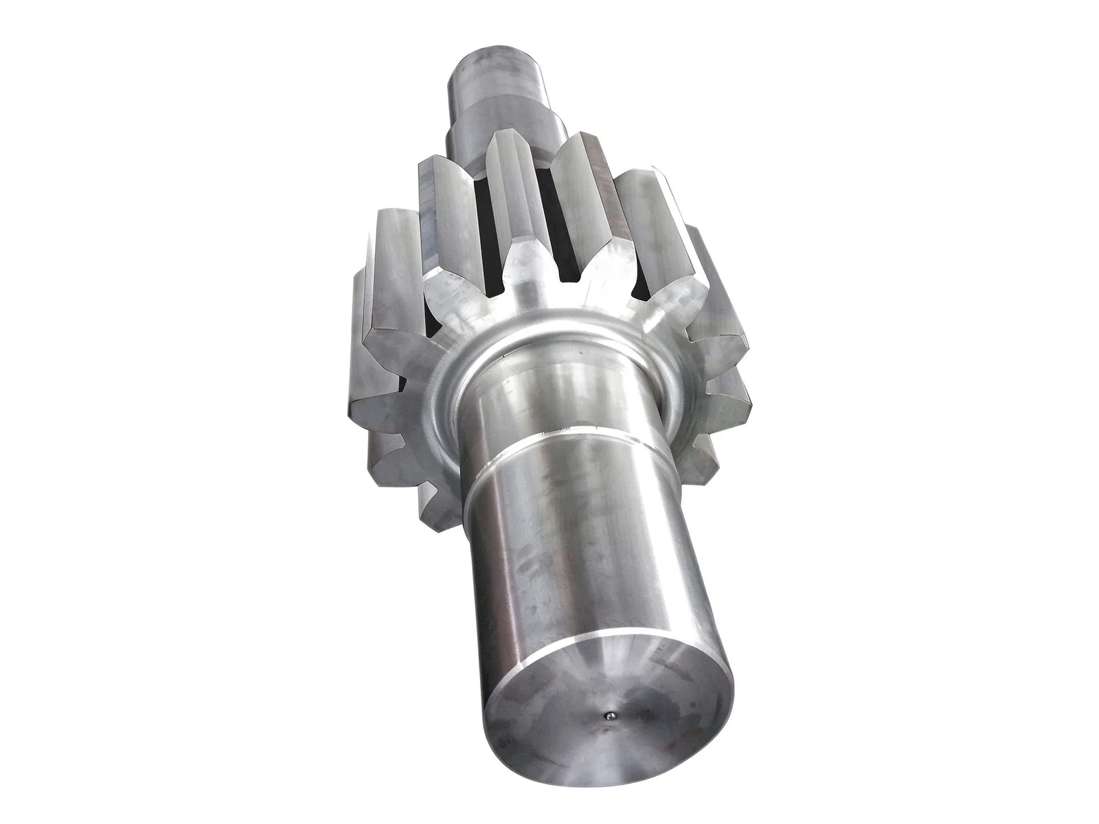
One-piece gear-and-shaft construction
The teeth are cut directly into the shaft blank, so there is no fitted joint or assembly clearance between gear and shaft. Coaxiality and transmission accuracy are higher, and the single-piece body resists torque and shock better than a built-up gear.
Both ends are stepped bearing journals with locating shoulders for heavy-duty bearings. The centre holes in the shaft ends serve as the datum for turning and grinding, and can also be used as inspection datums.
Tooth form and load capacity
Large-module, wide-face straight cylindrical teeth give high root strength and torque capacity and take shock loads. Straight teeth generate no axial force, so axial load on the bearings and assembly effort stay low — a good match for low-speed, heavy-load duty.
On the machining side, gear parts can be produced up to Ø10 000 mm outside diameter and modules within M60, with straight, helical, herringbone or internal teeth, plus tooth-surface quenching when required.
Materials and heat treatment
Blanks are usually forged alloy structural steels such as 42CrMo and 20CrMnTi, quenched and tempered or carburized and hardened, then the tooth flanks are finished to balance core toughness with surface hardness.
Blanks can also be castings, forgings or rolled rings, chosen to drawing and working conditions. Hardness and distortion after heat treatment are recorded part by part as the basis for grinding and assembly.
Inspection, customization and lead time
Tooth pitch, runout, hardness and ultrasonic testing are carried out in house, with dimensions and geometry checked to drawing; records are kept per batch for traceability.
Module, number of teeth, face width, journal sizes and centre-hole form can be made to your drawings, confirmed together with the mating gear parameters. Typical lead time is within 90 days, set by drawing and batch size.
Specifications
- Typical materials
- 42CrMo, 20CrMnTi
- Heat treatment
- Quenching and tempering / carburizing and hardening
- Construction
- Teeth cut on a one-piece forged shaft
- Tooth form
- Straight cylindrical teeth, large module, wide face
Common questions
- Can you machine this part to my drawing?
- Yes. Every part is quoted from the drawing. Send a PDF, DWG, DXF, STEP or IGES file with the material, quantity and any inspection requirements, and we reply within one working day.
- How are the material and heat treatment decided?
- They follow your drawing. The specification table shows the range normally used for this part type; the final material and heat treatment are confirmed with the quotation.
- What lead time and inspection come with the part?
- Lead time is set in the quotation and depends on material, size, quantity and inspection scope. Material verification, in-process checks and final inspection records are archived with the part, and any extra certification is agreed before production.
- How is the part packed for export?
- Export parts are rust-proofed and packed for the transport method and destination confirmed in the quotation, with lifting points and markings agreed before dispatch.
Every part is quoted from the drawing itself, not from a size band. Send it over and we answer with the process, the lead time and the tolerance we can hold.
Quote this part