Gears & PinionsGear shafts
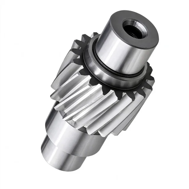
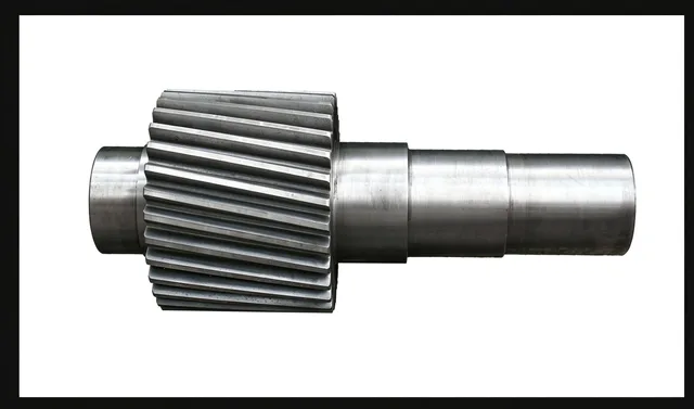
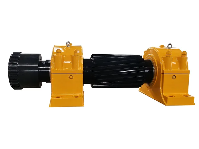
Spiral Bevel Gear Pair with Integral Pinion Shaft
A 90° shaft-angle spiral bevel gear set for speed reduction and torque transmission. Its pinion is integrated with the shaft to suit heavy-duty and shock-loaded drives.
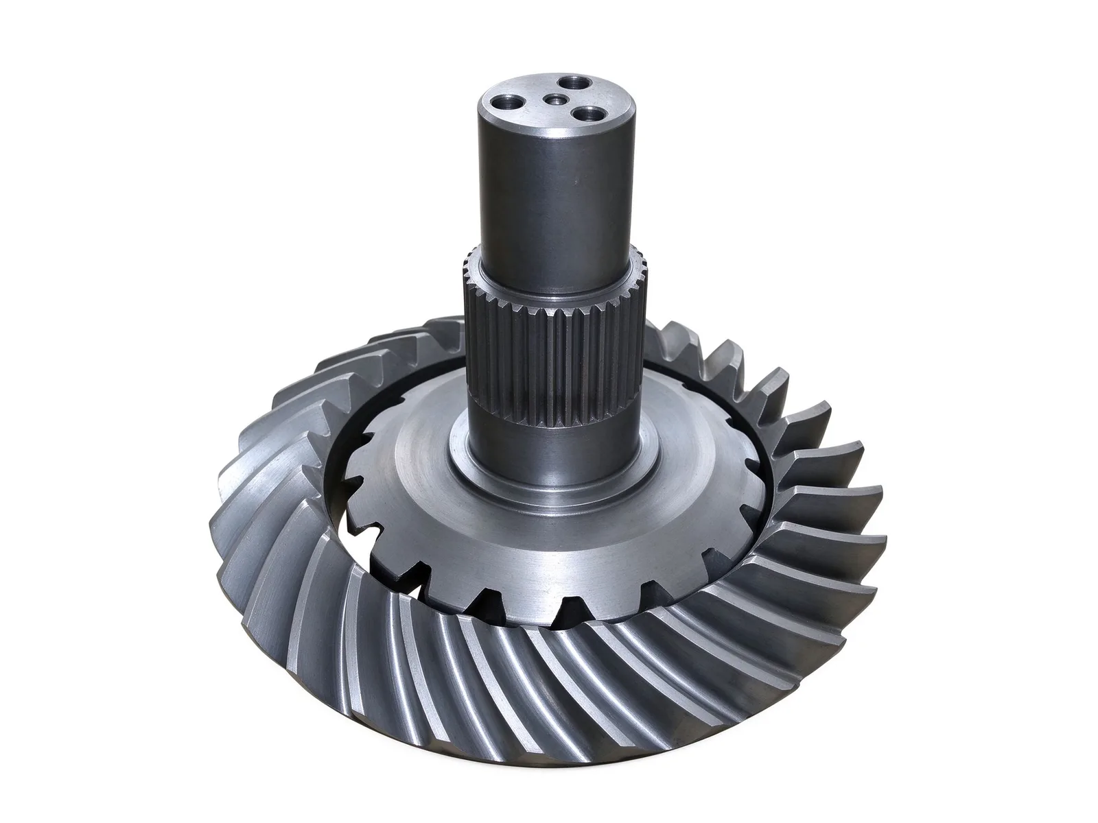
Spiral Bevel Gear Pair Design
This product is a spiral bevel gear pair for 90° shaft-angle power transmission, reducing speed and increasing torque in one stage. The curved tooth form supports smooth meshing and high load capacity, and the pinion is made as one piece with its shaft for heavy-duty and shock-loaded industrial and vehicle drivelines.
Typical applications include reduction units and driveline assemblies where a compact right-angle drive is required.
Gear and Shaft Machining
Gear cutting, shaft turning, spline milling, keyway machining, and hole drilling are handled in-house. For gear work, the shop can machine outside diameters up to Ø10,000 mm and modules up to M60, with blanks supplied as castings, forgings, or rolled rings.
Spiral bevel sets are commonly made from alloy carburizing steel and carburized and quenched to combine a wear-resistant tooth surface with an impact-resistant core. Quenching and tempering plus gear-surface induction hardening are also available for other gear configurations.
Inspection, Customization, and Delivery
Tooth spacing, runout, hardness, and ultrasonic testing are checked in-house, and dimensional and geometric results are recorded against the drawing. Final acceptance can include reports for the agreed inspection items.
Each pair is made to drawing or sample, with module, tooth count, ratio, spiral angle, accuracy grade, and surface hardness confirmed before production. Matching bearings, backlash, and mounting interfaces are reviewed against the customer's technical data. Typical lead time is within 90 days.
Specifications
- Max. outside diameter
- Ø10,000 mm
- Max. module
- M60
- Typical materials
- 45#, 42CrMo, ZG270-500
- Heat treatment
- Carburizing and quenching; quenching and tempering; gear-surface induction hardening
- Typical lead time
- Within 90 days
Common questions
- Can you machine this part to my drawing?
- Yes. Every part is quoted from the drawing. Send a PDF, DWG, DXF, STEP or IGES file with the material, quantity and any inspection requirements, and we reply within one working day.
- How are the material and heat treatment decided?
- They follow your drawing. The specification table shows the range normally used for this part type; the final material and heat treatment are confirmed with the quotation.
- What lead time and inspection come with the part?
- Lead time is set in the quotation and depends on material, size, quantity and inspection scope. Material verification, in-process checks and final inspection records are archived with the part, and any extra certification is agreed before production.
- How is the part packed for export?
- Export parts are rust-proofed and packed for the transport method and destination confirmed in the quotation, with lifting points and markings agreed before dispatch.
Every part is quoted from the drawing itself, not from a size band. Send it over and we answer with the process, the lead time and the tolerance we can hold.
Quote this part