Castings & ForgingsSteel castings
Articulated Heavy-Duty Double-Groove Sheave
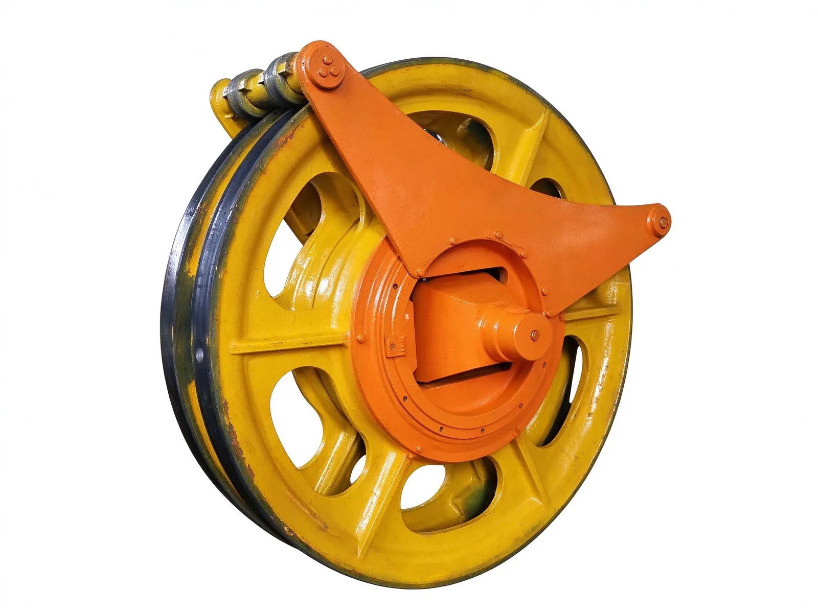
A cast steel sheave wheel with two machined rope grooves, carried on a heavy-duty bearing hub and hung from an articulated bracket that swings to follow the rope fleet angle.
Cast Steel Wheel and Machined Grooves
The wheel is cast as a single steel body with a box-plate web, lightening holes between the spokes and radial ribs that tie the rim to the hub. Normalizing and tempering follow casting, and the finish machining of the rim and hub is done after heat treatment so the groove profile and the bearing seat stay in line.
Two parallel circumferential grooves are machined into the rim to carry two wire ropes at once. The groove form keeps each rope tracking in its own path, limits sideways wander and reduces the bending and abrasion that shorten rope life.
Articulated Suspension Bracket
The wheel hub is pinned to a triangular suspension bracket, made from structural steel by welding or casting and painted as a separate assembly. The pin joint lets the wheel tilt with the rope as its lead angle changes, so the bracket absorbs part of the fleet angle instead of forcing the rope against the groove flanks.
A pin hole at the top of the bracket is used to hang the unit from a headframe or crane structure. Bracket geometry, pin diameter and hole position are made to the customer's drawing so the sheave fits the existing suspension layout.
Bearing Hub and Working Duty
A heavy-duty bearing, typically a self-aligning roller bearing, sits in the central hub and takes the radial load of the rope pull together with a limited axial component. The self-aligning seat tolerates slight deflection of the bracket under load and keeps the wheel turning freely through frequent starts and shock loads.
Capacity, Stress Relief and Inspection
Casting, stress relief, machining and assembly are handled in-house, with a maximum workpiece of 8 000 × 4 000 mm and a maximum unit weight of 20 t. Stress relief is our own process step; dimensional, geometric and UT/MT inspection are carried out as the drawing requires.
Customization covers wheel diameter, groove profile and rope diameter, number of grooves, bracket type and pin arrangement, and bearing selection. Parts are quoted and made to drawing, with a typical lead time of 8–12 weeks.
Specifications
- Max. workpiece size
- 8 000 × 4 000 mm
- Max. unit weight
- 20 t
- Stress relief
- In-house process
- Inspection
- Dimensional, geometric and UT/MT as required
- Typical lead time
- 8–12 weeks
Common questions
- Can you machine this part to my drawing?
- Yes. Every part is quoted from the drawing. Send a PDF, DWG, DXF, STEP or IGES file with the material, quantity and any inspection requirements, and we reply within one working day.
- How are the material and heat treatment decided?
- They follow your drawing. The specification table shows the range normally used for this part type; the final material and heat treatment are confirmed with the quotation.
- What lead time and inspection come with the part?
- Lead time is set in the quotation and depends on material, size, quantity and inspection scope. Material verification, in-process checks and final inspection records are archived with the part, and any extra certification is agreed before production.
- How is the part packed for export?
- Export parts are rust-proofed and packed for the transport method and destination confirmed in the quotation, with lifting points and markings agreed before dispatch.
Every part is quoted from the drawing itself, not from a size band. Send it over and we answer with the process, the lead time and the tolerance we can hold.
Quote this part