Gears & PinionsGear shafts
Assembled Herringbone Gear Shaft for Heavy-Duty Gearboxes
Assembled herringbone gear shaft for high-power gearboxes and reducers: two opposite-hand helical gear rims cancel axial thrust, cutting bearing load and running noise.
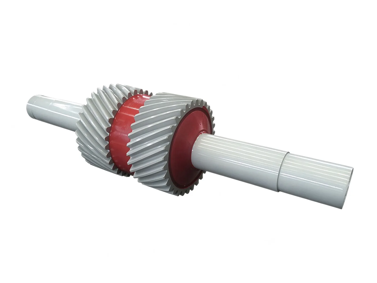
Assembled Double-Helical Tooth Form
The gear body is built from two helical gear rims of opposite hand, mounted symmetrically on the shaft so the pair works as a single herringbone gear. The opposing helix angles cancel the axial thrust generated by each helical mesh, which sharply reduces the axial load carried by the support bearings and extends bearing service life.
Because both rims mesh at the same time, contact ratio is high: torque transmission is smooth, running noise is low and load capacity is high, making this construction suited to high-speed, high-power drives in industrial gearboxes and reducers.
Machining and Heat Treatment Capability
Gear teeth are cut and ground in-house, with tooth forms covering spur, helical, herringbone and internal teeth. Maximum outside diameter we can machine is Ø8 000 mm and maximum module is M60; teeth can be hardened and ground after heat treatment, with a maximum hardening diameter of Ø8 000 mm.
Blanks can be supplied as castings, forgings or rolled rings, and typical materials include 45#, 42CrMo and ZG270-500. Heat treatment covers quenching and tempering plus high-frequency hardening of the tooth flank, so the working flank reaches a hard surface over a tough core.
Inspection and Quality Control
Tooth pitch, runout, hardness and ultrasonic testing are all checked in our own workshop before shipment, and reports are issued with the parts. Shaft journals, keyways, splines and end-face flange holes are machined on the same setup as the gear body to keep the gear-to-journal alignment consistent.
Typical lead time is 8 to 12 weeks depending on size, tooth form and heat treatment requirements.
Custom Scope
Shafts are produced to customer drawings. Module, tooth count, helix angle, accuracy grade, tooth hardness, journal dimensions, overall shaft length and hub locating dimensions are confirmed against the drawing or against measured samples before production.
Material grade, heat treatment parameters and the mating gearbox model are fixed per the technical documents supplied with the order, so the shaft matches the drive it will be installed in.
Specifications
- Max. outside diameter
- Ø8 000 mm
- Max. module
- M60
- Tooth forms
- Spur, helical, herringbone, internal
- Typical materials
- 45#, 42CrMo, ZG270-500
- Heat treatment
- Quenching and tempering, tooth-flank high-frequency hardening
- Typical lead time
- 8–12 weeks
Common questions
- Can you machine this part to my drawing?
- Yes. Every part is quoted from the drawing. Send a PDF, DWG, DXF, STEP or IGES file with the material, quantity and any inspection requirements, and we reply within one working day.
- How are the material and heat treatment decided?
- They follow your drawing. The specification table shows the range normally used for this part type; the final material and heat treatment are confirmed with the quotation.
- What lead time and inspection come with the part?
- Lead time is set in the quotation and depends on material, size, quantity and inspection scope. Material verification, in-process checks and final inspection records are archived with the part, and any extra certification is agreed before production.
- How is the part packed for export?
- Export parts are rust-proofed and packed for the transport method and destination confirmed in the quotation, with lifting points and markings agreed before dispatch.
Every part is quoted from the drawing itself, not from a size band. Send it over and we answer with the process, the lead time and the tolerance we can hold.
Quote this part