Gears & PinionsRing gears
Heavy-Duty Wide-Face Helical Driven Gear
Plate-type cast steel large gear with wide helical teeth, built as the driven stage for high-ratio, high-torque reduction in heavy-duty reducers and large rotary equipment drives.
Structure and Function
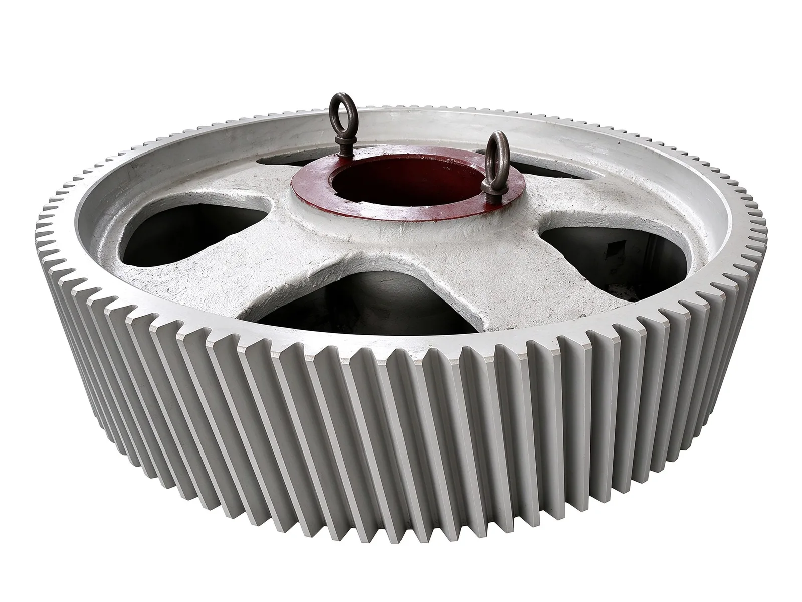
This is a one-piece plate-type large gear with wide helical teeth running on an external rim. The web carries lightening holes that cut rotating mass while keeping stiffness between the rim and the hub, and the hub bore is finished for a shaft fit. Two lifting eye bolts on the hub face let the part be slung safely during transport, assembly and maintenance.
As the driven stage of a heavy-duty train, the gear meshes with a smaller pinion to deliver a large reduction ratio and multiplied output torque at low speed. The wide helical face spreads load across several teeth in mesh and keeps meshing smoother and quieter than a straight-tooth design of the same size.
Machining Capability
Gear cutting, hobbing and finishing are handled in-house for external and internal tooth forms, including straight, helical, double-helical and internal teeth, with a maximum outside diameter of Ø8,000 mm and a maximum module of M60. Tooth-surface hardening is available up to Ø8,000 mm.
Blanks can be supplied as castings, forgings or rolled rings, and the tooth flanks, bore and mounting faces are machined in the same setup chain so that the bore, rim and tooth circle stay aligned.
Materials and Heat Treatment
Typical materials are 45#, 42CrMo and ZG270-500, selected against the torque, shock load and section size of the application. Heat treatment covers quenching and tempering for core toughness plus induction hardening of the tooth surface for wear resistance, with hardness and case depth checked on the finished part.
For cast and forged blanks, stress relief is carried out as an in-house operation before final machining to limit distortion after tooth cutting.
Quality Control and Customization
Tooth pitch, runout, hardness and ultrasonic testing are all inspected in-house, and dimensional, form-and-position, UT and MT checks are added where the drawing calls for them. Inspection records are issued with the part.
Gears are made to drawing or to a sample: module, tooth count, helix angle, face width, bore diameter, accuracy grade and mounting interface are all fixed per order, with a typical lead time of 8–12 weeks.
Specifications
- Max. outside diameter
- Ø8,000 mm
- Max. module
- M60
- Typical materials
- 45#, 42CrMo, ZG270-500
- Heat treatment
- Quenching and tempering; tooth-surface induction hardening
- Typical lead time
- 8–12 weeks
Common questions
- Can you machine this part to my drawing?
- Yes. Every part is quoted from the drawing. Send a PDF, DWG, DXF, STEP or IGES file with the material, quantity and any inspection requirements, and we reply within one working day.
- How are the material and heat treatment decided?
- They follow your drawing. The specification table shows the range normally used for this part type; the final material and heat treatment are confirmed with the quotation.
- What lead time and inspection come with the part?
- Lead time is set in the quotation and depends on material, size, quantity and inspection scope. Material verification, in-process checks and final inspection records are archived with the part, and any extra certification is agreed before production.
- How is the part packed for export?
- Export parts are rust-proofed and packed for the transport method and destination confirmed in the quotation, with lifting points and markings agreed before dispatch.
Every part is quoted from the drawing itself, not from a size band. Send it over and we answer with the process, the lead time and the tolerance we can hold.
Quote this part