Gears & PinionsGear shafts
Integrated Multi-Stage Transmission Gear Shaft
A one-piece gear shaft that combines multiple spur and helical gear sets, an external involute spline, and stepped bearing journals to provide multi-speed ratio changes in transmissions and reducers.
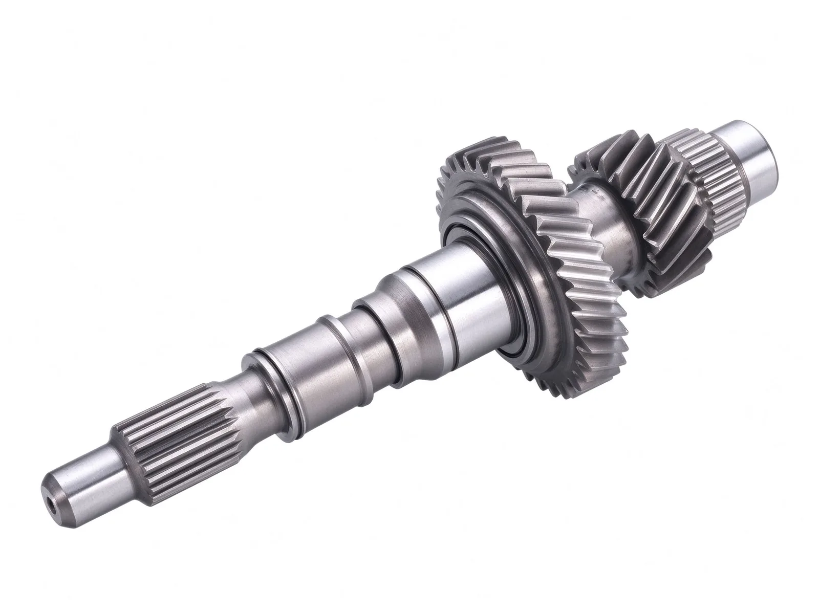
Integrated Multi-Gear Shaft Construction
This is a one-piece multi-stage gear shaft for manual transmissions, precision multi-stage reducers, engineering machinery gearboxes, and machine tool spindle gearboxes. Several gear sets with different tooth counts and tooth forms, including spur and helical teeth, are cut on a common shaft body, and each set provides a different gear ratio when it meshes with its mating gear.
The left end carries an external involute spline for a synchronizer, shift mechanism, or power take-off. Stepped journals locate rolling bearings, synchronizer components, spacers, and lock nuts, helping maintain gear mesh clearance and axial positioning.
Gear Cutting and Heat Treatment
Production typically starts from 20CrMnTi or 20CrMo alloy steel forgings. After carburizing and quenching, the tooth surfaces achieve high hardness and wear resistance while the core retains toughness for shifting shock and alternating loads. Gear and journal surfaces are precision ground to control form and position tolerances and to support low-noise, smooth transmission.
For gear work, our maximum machinable outside diameter is Ø8,000 mm and the maximum module is M60. Tooth forms include spur, helical, herringbone, and internal teeth, and the maximum quench diameter is 8,000 mm. Blanks can be castings, forgings, or rolled rings.
Inspection and Quality Control
Pitch, runout, hardness, and ultrasonic testing are checked in-house, and dimensions and geometric tolerances are inspected to the drawing. Inspection records can be provided with the shipment when required.
Custom Options and Applications
Custom gear shafts can be built to drawing or sample. Before production, we confirm module, tooth count, helix angle, spline specification, journal dimensions, overall length, material grade, and heat treatment requirements.
These shafts are commonly used in automotive manual transmissions, engineering machinery transmissions, precision multi-stage reducers, and machine tool spindle gearboxes where multi-speed ratio changes and torque output are required. Typical lead time is 8–12 weeks.
Specifications
- Typical materials
- 20CrMnTi, 20CrMo
- Blank type
- Alloy steel forging
- Heat treatment
- Carburizing and quenching
- Gear types
- Spur and helical
- Spline interface
- External involute spline
Common questions
- Can you machine this part to my drawing?
- Yes. Every part is quoted from the drawing. Send a PDF, DWG, DXF, STEP or IGES file with the material, quantity and any inspection requirements, and we reply within one working day.
- How are the material and heat treatment decided?
- They follow your drawing. The specification table shows the range normally used for this part type; the final material and heat treatment are confirmed with the quotation.
- What lead time and inspection come with the part?
- Lead time is set in the quotation and depends on material, size, quantity and inspection scope. Material verification, in-process checks and final inspection records are archived with the part, and any extra certification is agreed before production.
- How is the part packed for export?
- Export parts are rust-proofed and packed for the transport method and destination confirmed in the quotation, with lifting points and markings agreed before dispatch.
Every part is quoted from the drawing itself, not from a size band. Send it over and we answer with the process, the lead time and the tolerance we can hold.
Quote this part