Gears & PinionsGear shafts
Integral Helical Gear Shaft for Heavy-Duty Gearboxes
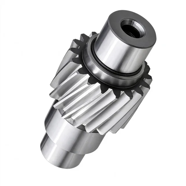
One-piece helical gear shaft that transmits high torque in heavy-duty gearboxes and reducers, with hardened, precision-ground teeth and stepped bearing journals.
One-Piece Gear and Shaft Body
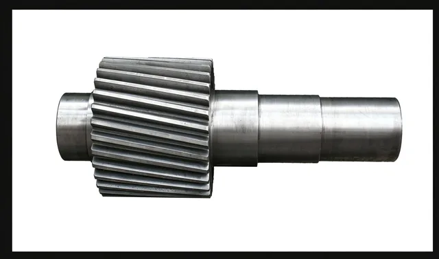
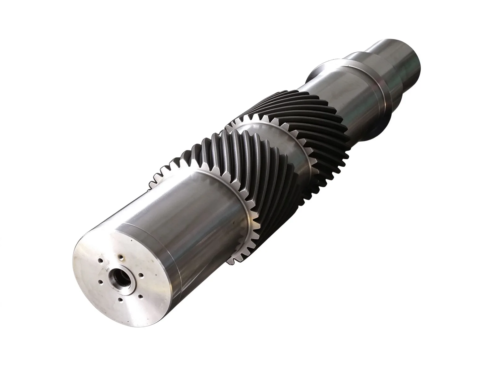
The gear teeth and shaft body are forged and machined as one piece, so there is no assembled fit between gear and shaft. This improves torsional stiffness, coaxiality, and resistance to shock loads compared with assembled gear designs.
The helical tooth form gives a high contact ratio for smooth, low-noise operation and high load capacity in medium-to-high speed, high-torque duty. Tooth flanks are hardened and precision ground.
Materials, Heat Treatment, and Gear Grinding
Common materials are 42CrMo and 20CrMnTi alloy steel forgings. Blanks can be quenched and tempered or carburized and hardened, depending on the required core toughness and tooth-surface hardness.
Gear cutting and grinding cover outside diameters up to Ø8,000 mm and modules up to M60, including straight, helical, herringbone, and internal tooth forms. High-frequency tooth-surface hardening is available up to Ø8,000 mm.
Bearing Journals and End-Face Features
Both ends have multi-step journals and locating shoulders that support bearings, spacers, and locking components and set axial position. The large-diameter shaft body raises resistance to torsion and deformation under high torque and alternating impact loads.
The shaft end is machined with a center hole for turning and grinding location and with axial threaded holes for axial locking, end-cover mounting, or lifting during assembly.
Quality Control, Applications, and Customization
Gear pitch, runout, hardness, and ultrasonic inspection can be checked in-house. Typical lead time is 8–12 weeks.
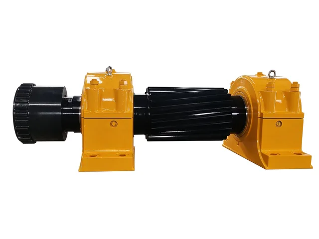
These shafts are commonly used in heavy-duty gearboxes, metallurgical mill drives, mine hoists, large crushers, and lifting and transport machinery. Dimensions, journal fits, tooth geometry, material, and heat treatment can be produced to drawings.
Specifications
- Typical materials
- 42CrMo, 20CrMnTi
- Heat treatment
- Quenching and tempering; carburizing and hardening
Common questions
- Can you machine this part to my drawing?
- Yes. Every part is quoted from the drawing. Send a PDF, DWG, DXF, STEP or IGES file with the material, quantity and any inspection requirements, and we reply within one working day.
- How are the material and heat treatment decided?
- They follow your drawing. The specification table shows the range normally used for this part type; the final material and heat treatment are confirmed with the quotation.
- What lead time and inspection come with the part?
- Lead time is set in the quotation and depends on material, size, quantity and inspection scope. Material verification, in-process checks and final inspection records are archived with the part, and any extra certification is agreed before production.
- How is the part packed for export?
- Export parts are rust-proofed and packed for the transport method and destination confirmed in the quotation, with lifting points and markings agreed before dispatch.
Every part is quoted from the drawing itself, not from a size band. Send it over and we answer with the process, the lead time and the tolerance we can hold.
Quote this part